



Blog
What Cat6A Patch Panel Do You Need for 10GbE and PoE++ in Europe?

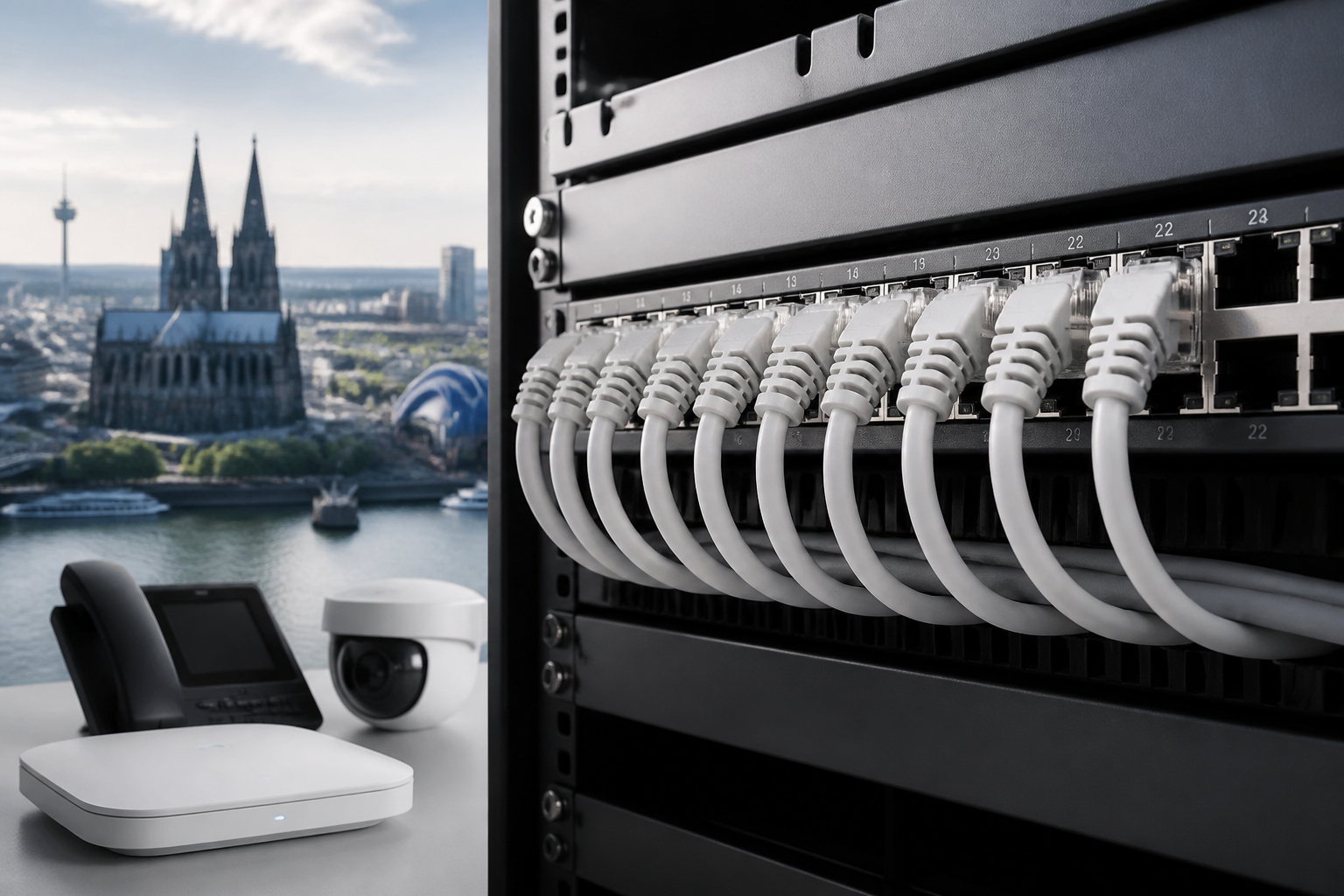
The right Cat6A patch panel for 10GbE and PoE++ is a standards-compliant, properly grounded panel that matches your cable type, connector system, rack layout, and power requirements. For most European installations, choose a 19-inch panel with clear port identification, reliable termination, strain relief, and a shielded design when using F/UTP, U/FTP, or S/FTP Cat6A cable.
A patch panel is passive: it does not create network speed or PoE power by itself. Its job is to terminate and organise horizontal cabling while maintaining the electrical performance of the permanent link. The cabling, patch cords, connectors, switch, powered devices, and installation quality must work together to deliver 10GbE and PoE++ reliably.
What to look for in a Cat6A patch panel for 10GbE and PoE++
Before comparing brands or port counts, define the complete channel. A suitable panel should support the following requirements:
- Category 6A performance: The panel should be designed and specified for Class EA or Category 6A permanent links, depending on the applicable cabling standard.
- 10GbE compatibility: The complete channel should support 10GBASE-T over the intended distance, with compatible Cat6A cable and patch cords.
- PoE++ readiness: For IEEE 802.3bt applications, the panel should provide dependable contact geometry, secure termination, and adequate thermal performance.
- Correct shielding: A shielded panel is normally the logical choice for shielded cable; an unshielded panel suits an unshielded cabling system.
- Rack compatibility: Check whether the panel is 19-inch, its height in rack units, and whether it includes rear cable management.
- Installation consistency: The panel, jacks, cable, patch cords, and tool should be from a compatible system or clearly rated for the same category.
Shielded or unshielded: which panel is better?
The panel must match the topology and earthing approach of the structured cabling system. A shielded Cat6A system typically uses shielded cable, shielded modules or jacks, and a shielded patch panel connected to the telecommunications bonding system. This can help control electromagnetic interference in areas with motors, variable-frequency drives, industrial equipment, dense power cabling, or large PoE loads.
An unshielded system can be appropriate in ordinary office environments when the cabling design is unshielded and separation from electrical services is maintained. Do not mix shielded and unshielded components casually. The resulting channel may be difficult to verify, and a shield that is not bonded correctly can create an inconsistent installation rather than a useful screening path.
Grounding considerations in Europe
A shielded patch panel should have a dependable bonding provision, such as a grounding stud, terminal, or rack-bonding arrangement. Connect it according to the site’s electrical and telecommunications bonding design. The rack itself should not be assumed to provide a complete earth path unless the installation has been designed and tested that way.
Follow the manufacturer’s instructions and the applicable national requirements. Where a project specification calls for permanent-link certification, test the installed channel with an appropriate field tester rather than relying only on continuity checks.
How PoE++ affects patch panel selection
PoE++ commonly refers to IEEE 802.3bt, which uses four pairs to deliver power to compatible devices. Typical applications include wireless access points, pan-tilt-zoom cameras, digital signage, building controllers, and other devices with higher power requirements than earlier PoE generations.
The patch panel does not negotiate or supply PoE power, but its contacts and terminations carry the current. That makes mechanical and thermal quality important. Look for a panel designed for current-carrying Ethernet applications and confirm the supplier’s PoE guidance, especially for higher-power Type 3 or Type 4 deployments.
- Use connectors and patch cords explicitly suitable for the expected PoE application.
- Follow the specified conductor strip length and termination method.
- Avoid damaged, loose, or poorly seated contacts.
- Keep bundles organised and follow the manufacturer’s bundle-size and temperature guidance.
- Do not exceed the cable manufacturer’s recommendations for ambient temperature or bundle density.
Higher current can increase heating inside dense cable bundles. A well-designed installation therefore considers the rack position, bundle routing, ambient conditions, and the total number of powered links. A panel that is mechanically compatible with Cat6A is not automatically the best choice for every high-density PoE++ environment.
Termination options: modular, punch-down, or feed-through
Modular keystone patch panels
A modular panel accepts individual Cat6A jacks or keystone modules. It is flexible when a rack contains several media types, when ports may need replacement, or when a structured cabling manufacturer uses a specific jack design. The main risk is component mismatch: the panel, modules, cable, and patch cords still need to form a compatible Category 6A system.
Punch-down patch panels
A fixed punch-down panel terminates horizontal cable directly on IDC terminals. It can provide a tidy and robust permanent-link arrangement when the termination block, cable diameter range, pair layout, and installation tool are compatible. Check whether the panel supports solid conductors and the cable construction selected for the project.
Feed-through patch panels
Feed-through panels use factory-terminated ports at the front and rear. They can simplify moves, adds, and changes, but they add connector interfaces to the link. Verify the stated category performance and ensure the connected modules and patch cords are also suitable for 10GbE and PoE++.
Port count, rack height, and cable management
A common choice is a 24-port, 1U panel, but the best size depends on the rack and the number of outlets. A 48-port panel can save rack space, while a lower-density layout may improve access, bend-radius control, and thermal management.
When planning the rack, allow space for:
- Horizontal or vertical patch-cord management.
- Rear cable support and strain relief.
- Service loops without exceeding the minimum bend radius.
- Clear port labelling and room for future changes.
- Separation between data bundles and mains or high-noise equipment.
Do not force a large number of thick Cat6A cables into a narrow rear channel. Cable diameter varies significantly between products, particularly for shielded, low-smoke, zero-halogen, and higher-performance constructions. Check the panel’s cable-entry capacity before ordering.
European standards and documentation to check
For a European project, ask the supplier for technical documentation rather than relying only on a product name. Depending on the installation, relevant references may include EN 50173, ISO/IEC 11801, the applicable IEC component and testing standards, and IEEE 802.3 Ethernet specifications.
Confirm the following points:
| Item | What to verify |
|---|---|
| Category rating | Cat6A or the required Class EA component and link performance. |
| PoE support | Manufacturer guidance for IEEE 802.3bt and the intended power class. |
| Shielding | Screen continuity, bonding provision, and compatibility with the selected cable. |
| Connector type | IDC, keystone, or feed-through design and supported conductor sizes. |
| Fire and environmental details | Relevant product declarations and cable CPR classification where the project requires it. |
| Testing | Permanent-link or channel test limits and the recommended certification procedure. |
Product compliance markings and declarations should be reviewed in context. A patch panel’s documentation does not replace the requirements that apply to the installed cable, rack, electrical bonding, or building project.
Installation practices for dependable 10GbE and PoE++
- Plan the link: Document outlet locations, rack positions, cable routes, patch-cord lengths, and powered-device requirements.
- Maintain cable geometry: Avoid excessive pulling force, sharp bends, kinks, and unnecessary untwisting near the termination.
- Use the correct wiring scheme: Apply T568A or T568B consistently throughout the project according to the design.
- Bond shielded hardware: Terminate screens and bond the panel as specified; do not leave shield continuity to chance.
- Label both ends: Use permanent identifiers that match the rack schedule and outlet numbering.
- Control the bundle: Use suitable hook-and-loop management and avoid over-compressing high-density PoE bundles.
- Certify the result: Test the completed permanent links with a calibrated tester configured for the selected category and standard.
Practical rule: Choose the patch panel as part of a complete cabling channel, not as an isolated rack accessory. The weakest compatible component can limit the performance of the whole link.
Common selection mistakes to avoid
- Choosing by label alone: A panel marked Cat6A may still have limitations on cable diameter, conductor type, or PoE use.
- Ignoring patch cords: Short cords are part of the channel and should match the required category and application.
- Mixing shield systems: Combining screened and unscreened parts without a defined design can undermine bonding and verification.
- Overlooking space: A 1U panel may fit the rack but leave insufficient room for bend radius and service access.
- Skipping certification: Link lights show basic connectivity, not compliance with 10GbE channel performance.
- Assuming PoE power is unlimited: The switch, cable bundle, connector system, and powered device must all support the intended power level.
Recommended specification checklist
For a typical European commercial network, a practical specification might call for a 19-inch, 1U or 2U Cat6A panel with the required port density, clear numbering, rear cable support, and termination instructions. Select shielded or unshielded construction to match the permanent cabling design. For PoE++, add explicit manufacturer confirmation for IEEE 802.3bt applications and review bundle-management guidance.
For larger or mission-critical installations, also specify the approved cable family, jack or module, patch-cord type, rack-bonding method, test limits, labelling scheme, and acceptance documentation. This approach makes procurement more reliable and reduces disputes during commissioning.
Key takeaways
- The best Cat6A patch panel for 10GbE and PoE++ is one that matches the entire channel, not merely the printed category label.
- Use shielded components with a defined bonding design where electromagnetic interference or the project specification requires it.
- For PoE++, verify current-carrying suitability, connector quality, bundle limits, and thermal conditions.
- Check port density, rack height, cable-entry space, bend radius, and service access before installation.
- Certify completed links with the appropriate field test equipment.
Frequently asked questions
Do I need a special patch panel for 10GbE?
You need a patch panel and complete channel designed to meet Cat6A or the required Class EA performance. The panel alone does not guarantee 10GbE; cable, modules, patch cords, terminations, and installation quality must also comply.
Can a Cat6A patch panel carry PoE++?
It can be used in a PoE++ link when the manufacturer confirms suitability for the intended IEEE 802.3bt application and the complete channel is correctly installed. The panel passes power but does not generate or negotiate it.
Should I choose a shielded Cat6A patch panel?
Choose shielded construction when the cabling system uses shielded cable and the project provides a correct bonding arrangement, or when the environment requires additional electromagnetic protection. Use unshielded components for a deliberately unshielded system.
Is a 24-port 1U panel enough for a European office?
It may be suitable, but the answer depends on outlet count, future capacity, cable diameter, bend radius, and rack access. Compare the panel’s port density and rear cable space with the actual installation plan.
Do I need to certify a 10GbE patch panel installation?
For a professional structured cabling installation, certify the completed permanent links or channels using a calibrated tester and the applicable category limits. Basic link connectivity does not prove 10GbE performance.
{“@context”:”https://schema.org”,”@type”:”FAQPage”,”mainEntity”:[{“@type”:”Question”,”name”:”Do I need a special patch panel for 10GbE?”,”acceptedAnswer”:{“@type”:”Answer”,”text”:”You need a patch panel and complete channel designed to meet Cat6A or the required Class EA performance. The panel alone does not guarantee 10GbE; cable, modules, patch cords, terminations, and installation quality must also comply.”}},{“@type”:”Question”,”name”:”Can a Cat6A patch panel carry PoE++?”,”acceptedAnswer”:{“@type”:”Answer”,”text”:”It can be used in a PoE++ link when the manufacturer confirms suitability for the intended IEEE 802.3bt application and the complete channel is correctly installed. The panel passes power but does not generate or negotiate it.”}},{“@type”:”Question”,”name”:”Should I choose a shielded Cat6A patch panel?”,”acceptedAnswer”:{“@type”:”Answer”,”text”:”Choose shielded construction when the cabling system uses shielded cable and the project provides a correct bonding arrangement, or when the environment requires additional electromagnetic protection. Use unshielded components for a deliberately unshielded system.”}},{“@type”:”Question”,”name”:”Is a 24-port 1U panel enough for a European office?”,”acceptedAnswer”:{“@type”:”Answer”,”text”:”It may be suitable, but the answer depends on outlet count, future capacity, cable diameter, bend radius, and rack access. Compare the panel’s port density and rear cable space with the actual installation plan.”}},{“@type”:”Question”,”name”:”Do I need to certify a 10GbE patch panel installation?”,”acceptedAnswer”:{“@type”:”Answer”,”text”:”For a professional structured cabling installation, certify the completed permanent links or channels using a calibrated tester and the applicable category limits. Basic link connectivity does not prove 10GbE performance.”}}]}
One thought on “What Cat6A Patch Panel Do You Need for 10GbE and PoE++ in Europe?”
Comments are closed.