



Blog
Punch-Down vs Feed-Through Patch Panels: Which Should You Use in a European Network Installation?

Quick answer: Choose a punch-down patch panel for permanent horizontal cabling where secure termination, controlled cable management and long-term stability matter most. Choose a feed-through patch panel when you need fast installation, simple front-to-back patching and minimal termination work. In the punch down vs feed through patch panel decision, the right option depends on whether the panel is part of the permanent link or mainly a convenient connection point.
Both designs can be suitable for copper Ethernet networks in offices, industrial sites, schools, healthcare buildings and data rooms. However, they organise cabling differently, which affects installation time, troubleshooting, documentation, future changes and the quality of the finished rack. This guide explains the practical differences so you can select a panel that fits your European network installation and applicable cabling requirements.
Punch down vs feed through patch panel: the essential difference
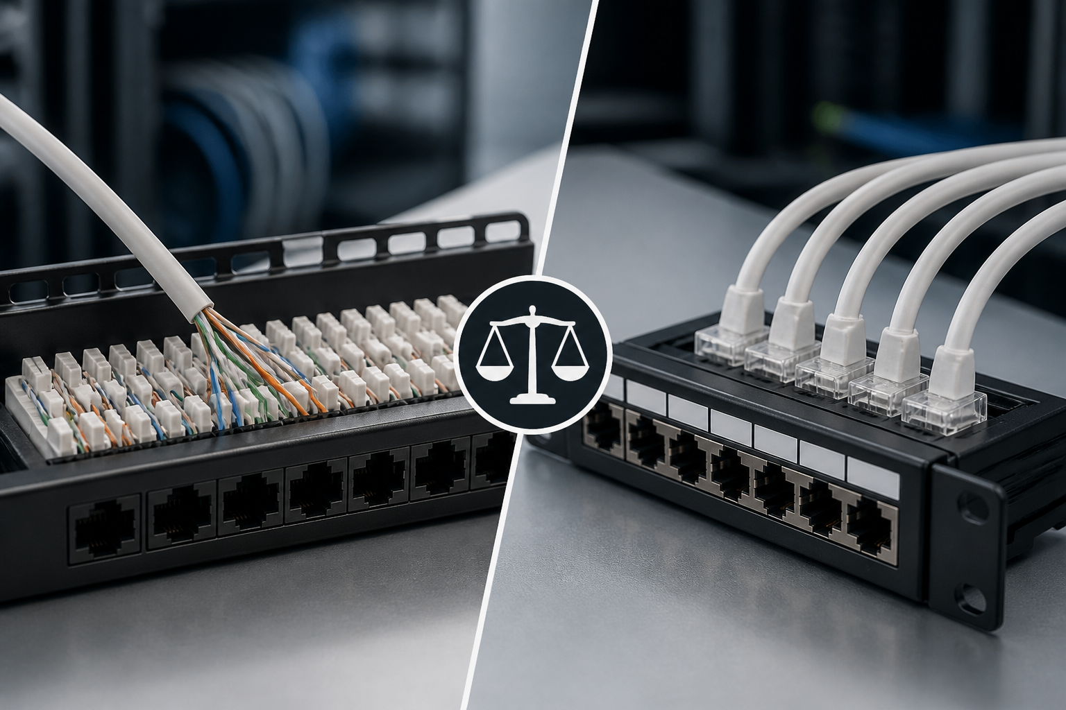
A punch-down patch panel terminates solid horizontal cable on the rear using insulation-displacement connection (IDC) terminals. Each conductor is placed into a colour-coded slot and seated with a compatible punch-down tool. Short patch leads then connect the panel’s front ports to switches, routers or other equipment.
A feed-through patch panel has RJ45 sockets on both sides. Instead of terminating the permanent cable directly on the panel, an installer normally uses pre-terminated copper patch cords or connects the rear ports to another component with modular plugs. The panel acts as a pass-through connection point between the front and rear of the rack.
| Feature | Punch-down patch panel | Feed-through patch panel |
|---|---|---|
| Rear connection | IDC termination | RJ45 socket |
| Typical cable type | Solid horizontal installation cable | Pre-terminated patch leads or modular connections |
| Installation speed | Requires termination and testing | Generally faster to connect |
| Cable management | Designed for organised permanent cabling | Can require more rear patch-cord management |
| Best use | Permanent links and structured cabling | Flexible patching and rapid deployment |
| Change management | Best when outlets remain fixed | Convenient when connections change often |
How a punch-down patch panel works
In a conventional structured cabling layout, each permanent cable runs from a telecommunications outlet to a rack or cabinet. At the rack, the cable enters the rear of a punch-down patch panel. The installer separates the pairs, follows the panel’s T568A or T568B colour code and seats each conductor into its IDC termination.
The terminated port is then tested as part of the permanent link or channel, depending on the design. On the front, a patch lead connects the outlet’s panel port to an active switch port. This arrangement separates the fixed building cabling from equipment connections, making moves, adds and changes easier to control.
Advantages of punch-down panels
- Good for permanent cabling: Solid installation cable is normally intended to be terminated at an IDC block rather than repeatedly fitted with field plugs.
- Orderly rack layout: The cable bundle enters the rear once, while short patch leads remain accessible at the front.
- Strong documentation: Port numbers can correspond directly to rooms, outlets, cabinets and cable records.
- Reduced rear-side plug congestion: The back of the rack does not need a large collection of RJ45 patch leads.
- Suitable for structured cabling practice: The design clearly distinguishes permanent links from equipment patching.
Limitations of punch-down panels
- Termination takes longer than inserting pre-made patch leads.
- An installer needs the correct punch-down tool and appropriate training.
- Incorrect conductor seating, excessive untwist or poor strain relief can affect performance.
- Changing a permanent port may require re-termination and a new test result.
- The panel and cable must be compatible with the required category and shielding arrangement.
How a feed-through patch panel works
A feed-through patch panel provides modular RJ45 connections at the front and rear. A network cable or patch lead enters from the rear, and a second patch lead connects from the front to a switch or another device. The internal connection is already assembled, so the installer does not need to place individual conductors into IDC terminals at the panel.
This approach is particularly useful when the cabling is already terminated, when equipment must be connected quickly or when a rack needs a clearly labelled interface between two groups of patch leads. Feed-through panels are also common in environments where patching flexibility is more important than using the panel as the termination point for fixed horizontal cable.
Advantages of feed-through panels
- Fast deployment: Pre-terminated leads can be connected with little specialist termination work.
- Simple visual changes: Technicians can move a connection by unplugging and reconnecting a patch lead.
- Consistent modular interface: Both sides use familiar RJ45 connections.
- Useful for temporary or evolving layouts: They can suit staging areas, laboratory racks and frequently reconfigured systems.
- Lower termination skill requirement: The installation relies less on manual pair termination at the panel.
Limitations of feed-through panels
- They can create more patch cords behind the rack, making airflow, bend radius and identification harder to manage.
- Each additional plug-and-socket interface is a potential point for contamination, wear or accidental disconnection.
- They may not be the most efficient choice for large numbers of fixed horizontal cables.
- Patch leads can become difficult to trace if labels and documentation are inconsistent.
- Category, shielding and component compatibility still need to be verified; a feed-through design is not automatically suitable for every Ethernet class.
Which panel is better for a European network installation?
There is no universal winner. The correct selection should follow the cabling architecture, installation environment and project requirements. European structured cabling projects may be designed with reference to standards such as EN 50173 and ISO/IEC 11801, together with applicable national rules, customer specifications and manufacturer instructions. These documents define the performance and topology expectations; they do not make every project use one particular patch-panel style.
Use the following decision points before ordering hardware:
1. Is the cable permanent or frequently changed?
For fixed cables running to work-area outlets, access points, cameras or building systems, a punch-down panel is usually the more natural fit. The cable remains in place and the front patch lead provides the operational connection. For frequently changing links, a feed-through panel may reduce the effort required for rearrangement.
2. Where will the cable be terminated?
Do not assume that a feed-through panel can accept any cable directly. Confirm whether the rear ports are intended for patch cords, field-terminable plugs or a particular modular system. Solid horizontal cable, stranded patch cable and shielded cable can have different termination requirements.
3. How much space is available behind the rack?
A feed-through arrangement can require a row of rear patch leads, their bend radius and a route for labelling. In a shallow cabinet or a dense data room, this can make access difficult. A punch-down panel often presents a more compact permanent termination, although it still requires adequate rear cable support and working clearance.
4. What level of future change is expected?
In a stable office installation, permanent ports may remain unchanged for years, making punch-down termination practical. In a laboratory, co-location facility or temporary project space, connections may be moved regularly. In that case, modular feed-through connections can save time, provided the extra patching is controlled.
5. What will the testing and handover process require?
Every copper link should be tested with equipment appropriate to the specified category and topology. The installer should record port identifiers, cable destinations, test results and any deviations. A panel that is quick to install is not a substitute for correct certification, labelling and documentation.
Performance considerations: category, shielding and PoE
The panel type alone does not determine network speed or reliability. Performance depends on the complete channel: cable, connectors, patch cords, patch panel, installation workmanship and active equipment. A Cat6A system, for example, needs compatible Cat6A components and suitable installation practices throughout the link.
For shielded networks, check that the panel, cable, connectors, rack bonding and patch leads form a compatible system. A shielded panel connected to unsuitable unshielded components may not deliver the intended solution. Follow the manufacturer’s bonding instructions and local electrical requirements rather than improvising a grounding method.
Power over Ethernet also deserves attention. If the network will supply wireless access points, cameras, phones or other powered devices, select components rated for the planned PoE application. Verify conductor size, contact construction, temperature conditions, bundle guidance and the manufacturer’s current or power limits. Poor connections can create heat or intermittent faults even when basic link testing initially passes.
Installation best practices
- Plan the rack elevation: Position patch panels, switches, cable managers and power equipment so patch leads have short, clear routes.
- Keep permanent cabling separate from patching: Support horizontal cables without placing pressure on terminations or exceeding the specified bend radius.
- Use one wiring scheme consistently: Follow the selected T568A or T568B scheme at both ends of the link.
- Control pair untwist: Preserve the cable geometry as close to the termination as the component instructions permit.
- Label both ends: Use durable labels that match drawings, cabinet identifiers and port records.
- Respect category compatibility: Do not mix components casually, particularly in higher-frequency or shielded installations.
- Test after completion: Inspect, certify and document each link before the rack is closed or handed over.
- Leave room for maintenance: Avoid filling every cable-management channel so technicians can access ports safely later.
Cost and maintenance comparison
The purchase price is only one part of the decision. Punch-down panels may involve more initial labour because each permanent cable must be prepared, terminated and tested. However, the result can be easier to maintain when the cable routes and outlets are fixed. Feed-through panels can reduce initial termination time, but the project may need more patch leads, rear cable management and replacement stock.
Maintenance also differs. With punch-down panels, a fault investigation can focus on the permanent termination, patch lead and switch port as separate sections. With feed-through panels, technicians should inspect both front and rear connectors and confirm that patch leads are correctly identified. In either design, clear records are often more valuable than the small difference in panel purchase price.
Practical rule: terminate fixed building cable once, patch equipment at the front and document every port. If the design requires repeated changes at the rear of the rack, reconsider whether a feed-through panel or a different distribution layout would be more suitable.
Common selection mistakes to avoid
- Using solid cable as if it were a patch lead: Select connectors and panels designed for the actual cable construction.
- Ignoring rear access: A panel may fit the rack while still being difficult to terminate or service.
- Mixing shielded and unshielded hardware without a plan: Confirm the complete bonding and compatibility approach.
- Overlooking bend radius: Tight cable bundles can damage performance and make future work unsafe.
- Choosing by port count alone: Consider depth, cable management, labelling, category, shielding and certification requirements.
- Skipping acceptance testing: Link lights show connectivity, not necessarily compliance with the required cabling performance.
Final recommendation
For most permanent office and building structured-cabling installations, a correctly installed punch-down patch panel is the sensible default. It provides a clean boundary between fixed cabling and active equipment, supports organised documentation and avoids unnecessary rear patch-cord congestion.
A feed-through patch panel is a strong alternative when speed, modularity and frequent rearrangement are the main priorities. It can work well in flexible racks, temporary deployments and controlled interconnection areas. Before choosing, confirm the cable type, category, shielding, PoE requirements, rack depth and testing plan.
The best answer to the punch down vs feed through patch panel question is therefore architectural rather than purely financial: use punch-down termination for stable permanent links, and feed-through connectivity for flexible modular patching. Whichever option you choose, compatible components, careful installation, accurate labels and documented test results determine the quality of the finished network.
Frequently asked questions
Is a punch-down patch panel better than a feed-through patch panel?
Neither is always better. A punch-down panel is usually better for permanent horizontal cabling and orderly structured installations. A feed-through panel is often better when connections must be installed or changed quickly using pre-terminated patch leads.
Can a feed-through patch panel be used with solid-core Ethernet cable?
Only if the specific panel and its rear connection system are designed for that cable. Many feed-through panels are intended for modular patch cords rather than direct termination of solid horizontal cable. Check the manufacturer’s cable and connector compatibility instructions.
Do punch-down panels support Cat6A and PoE?
They can, provided the panel is rated for the required category and PoE application and is installed with compatible cable, patch leads and connectors. The complete channel should be tested and installed according to the component manufacturer’s guidance.
Which patch panel is easier to troubleshoot?
Both can be straightforward when ports are labelled and documented. Punch-down panels often make the permanent-link boundary clear, while feed-through panels make physical reconnection simple. Feed-through designs may require closer inspection of additional rear patch leads and connectors.
Should I choose T568A or T568B?
Either wiring scheme can be used when applied consistently. Follow the project specification, existing site convention and the patch panel’s colour markings. Do not mix schemes at the ends of a normal straight-through link.
Does a feed-through panel reduce network latency?
No meaningful performance advantage should be assumed from the panel style alone. Link performance depends on the complete cabling channel, component quality, installation and testing. Additional connectors can introduce more points that need to be maintained correctly.
{“@context”:”https://schema.org”,”@type”:”FAQPage”,”mainEntity”:[{“@type”:”Question”,”name”:”Is a punch-down patch panel better than a feed-through patch panel?”,”acceptedAnswer”:{“@type”:”Answer”,”text”:”Neither is always better. A punch-down panel is usually better for permanent horizontal cabling and orderly structured installations. A feed-through panel is often better when connections must be installed or changed quickly using pre-terminated patch leads.”}},{“@type”:”Question”,”name”:”Can a feed-through patch panel be used with solid-core Ethernet cable?”,”acceptedAnswer”:{“@type”:”Answer”,”text”:”Only if the specific panel and its rear connection system are designed for that cable. Many feed-through panels are intended for modular patch cords rather than direct termination of solid horizontal cable. Check the manufacturer’s cable and connector compatibility instructions.”}},{“@type”:”Question”,”name”:”Do punch-down panels support Cat6A and PoE?”,”acceptedAnswer”:{“@type”:”Answer”,”text”:”They can, provided the panel is rated for the required category and PoE application and is installed with compatible cable, patch leads and connectors. The complete channel should be tested and installed according to the component manufacturer’s guidance.”}},{“@type”:”Question”,”name”:”Which patch panel is easier to troubleshoot?”,”acceptedAnswer”:{“@type”:”Answer”,”text”:”Both can be straightforward when ports are labelled and documented. Punch-down panels often make the permanent-link boundary clear, while feed-through panels make physical reconnection simple. Feed-through designs may require closer inspection of additional rear patch leads and connectors.”}},{“@type”:”Question”,”name”:”Should I choose T568A or T568B?”,”acceptedAnswer”:{“@type”:”Answer”,”text”:”Either wiring scheme can be used when applied consistently. Follow the project specification, existing site convention and the patch panel’s colour markings. Do not mix schemes at the ends of a normal straight-through link.”}},{“@type”:”Question”,”name”:”Does a feed-through panel reduce network latency?”,”acceptedAnswer”:{“@type”:”Answer”,”text”:”No meaningful performance advantage should be assumed from the panel style alone. Link performance depends on the complete cabling channel, component quality, installation and testing. Additional connectors can introduce more points that need to be maintained correctly.”}}]}
2 thoughts on “Punch-Down vs Feed-Through Patch Panels: Which Should You Use in a European Network Installation?”
Comments are closed.